English
 Español
  Português
  русский
  Français
  日本語
日本語  Deutsch
  tiếng Việt
  Italiano
  Nederlands
  ภาษาไทย
  Polski
  한국어
한국어  Svenska
  magyar
  Malay
Malay  বাংলা ভাষার
  Dansk
Dansk  Suomi
Suomi  हिन्दी
  Pilipino
  Türkçe
  Gaeilge
  العربية
  Indonesia
  Norsk
Norsk  تمل
تمل  český
český  ελληνικά
  український
  Javanese
  فارسی
فارسی  தமிழ்
தமிழ்  తెలుగు
  नेपाली
  Burmese
  български
  ລາວ
ລາວ  Latine
  Қазақша
  Euskal
  Azərbaycan
  Slovenský jazyk
  Македонски
  Lietuvos
  Eesti Keel
  Română
  Slovenski
  मराठी
मराठी  Srpski језик


У дома
>
Продукти > Metal Chip Briquetting Machine
>
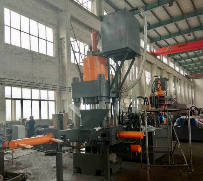
Iron filings/aluminum filings/cast iron filings parallel


Iron filings/aluminum filings/cast iron filings parallel
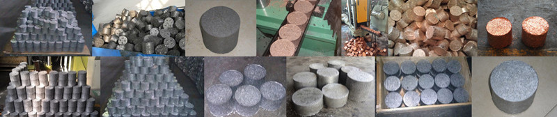
The crumb cake machine is suitable for aluminum alloy profile plants, steel casting plants, aluminum casting plants, copper casting plants, etc. It can remove aluminum scrap, aluminum dust, steel scrap, steel slag, steel pin, iron scrap, copper scrap, copper rice, zinc scrap , Lead scrap and other briquette
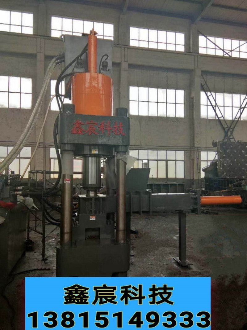
Модел:Y83
Изпратете запитване
Описание на продукта
630 тона стърготини и машина
Chip and machine, chip and machine manufacturer, hydraulic chip and machine, cast iron chip cake machine, steel powder chip machine, titanium chip machine, aluminum chip machine, automatic metal chip machine, high-capacity aluminum chip machine Parallel machine. Copper pin chip parallel machine, steel chip cake machine, waste lead chip cake machine
1. Употреба и характеристики
(1) Purpose
1. It is mainly used to press various metal scraps (cast iron scraps, copper scraps, aluminum scraps, etc.) into blocks through special molds, which facilitates the transportation and processing of metal scraps. It is used in steel plants, non-ferrous metal plants, and smelting. Ideal equipment for factories.
2. Тази машина е оборудвана с подходящи ножове, форми и други спомагателни инструменти и може да се използва и за корекция, пресоване, формоване, разтягане и обработка под налягане с общо предназначение, където изискванията за рязане и прецизност не са високи.
(2) Features
1. Тази машина приема хидравлична трансмисия, работеща гладко и с ниско ниво на шум.
2. Тази машина приема джогинг, единично и непрекъснато преобразуване на работата, с добра автоматизация, удобна работа и висока производствена ефективност.
2. Цялостна структура и принцип на работа
1. Overall structure The machine is mainly composed of mechanical system (main unit part), electrical system, hydraulic system, etc.
(1) The main engine is mainly composed of a main pressing mechanism and a pushing mechanism.
1. Основният притискащ механизъм е съставен от горна греда, долна греда, изправена колона и притискащ цилиндър за материал. Горната греда, долната греда и средната греда са заварени конструктивни части. Горната и долната греда са съставени от изправени колони, изправени капачки и изправени гайки, за да образуват основната рамка на основната рамка. Цилиндърът под налягане е с предна фланцова конструкция и е фиксиран върху горната греда. Буталният прът на цилиндъра с материал е свързан с горната матрица чрез вътрешни резби, а горната матрица се задвижва от масления цилиндър, за да се движи нагоре и надолу линейно. Масленият цилиндър под налягане е комбиниран маслен цилиндър, който е съставен от бутален еднодействащ главен маслен цилиндър под налягане и бързо работещ маслеен цилиндър. Бързо работещият маслен цилиндър е маслена бутилка с двойно действие на бутало с бутала, направляващи втулки и др. И уплътнителен пръстен. Долната греда се удвоява като работна платформа, оборудвана с помощни форми и бутащи цилиндри.
2. The pushing mechanism is composed of a pushing cylinder and auxiliary molds. The pushing cylinder is a piston type double-acting cylinder, which is fixed on the lower beam of the main machine with a front flange structure, and the front end is connected with the ejection pad of the auxiliary mold. The auxiliary mold is composed of an upper mold, a lower fixed mold base, a mold release pad, an inner mold sleeve, a lower mold pressing plate, and a feeding hopper. The upper mold is connected to the material pressing oil cylinder with external threads and the piston rod uses the material pressing oil cylinder to move up and down to compact the material in the inner mold sleeve. The lower fixed mold base is fixed on the lower beam with screws, and a surface-treated wear-resistant inner mold sleeve and die pad are installed in the middle, and the inner mold sleeve is fixed in the lower fixed mold base with a molding plate (see the attached mold structure diagram).
3. The hydraulic oil cylinder is composed of a material pressing oil cylinder and a material pushing oil cylinder. The pressure oil cylinder is composed of a main pressure oil cylinder and a quick work feed oil cylinder. The main pressure oil cylinder is a piston single-acting oil cylinder and also adopts a piston structure. Except for the front cavity without oil, the structure is the same as the fast work feed oil cylinder and the push oil cylinder Consistent. The quick-working oil inlet cylinder and the pushing oil cylinder are both piston-type double-acting oil cylinders. The piston is equipped with a sealing ring to form two oil chambers in the cylinder. When the high pressure oil acts on the rear cavity (also known as the large cavity) or the front cavity (Also known as small cavity) when pushing the piston to make a straight reciprocating motion in the cylinder, to achieve the purpose of driving the moving parts. At the same time, the cylinder port is provided with a guide sleeve for supporting, guiding and sealing the piston rod.
(2) The electrical system is composed of two parts: a motor control circuit and an action control circuit.
(3) The hydraulic system is composed of oil tank, pump station, valve station, etc. The main engine is divided into two parts: the feed oil circuit and the main pressure oil circuit.
2. Принцип на работа
Add the material to be processed from the hopper to the lower mold inner mold sleeve, press the automatic button, the upper mold will compress the material down to the system set pressure and return for 1 to 2 seconds (set by plc) to unload, and the pusher cylinder returns When it is in place, the upper mold moves downward to extrude the metal chips in the inner mold sleeve out of the mold cavity and returns, and the push cylinder advances to push the compact out of the mold cavity, completing a work cycle.
Четири, електрическа система
(1) Overview It is powered by a 380 volt AC power supply and consists of two parts: the main circuit and the control circuit.
1. The main circuit is composed of two parts: the motor circuit and the emergency stop circuit, which is powered by a 380V power supply. The motor circuit directly supplies power to a y-type three-phase asynchronous motor from the circuit power supply to drive a plunger pump and a gear pump. The emergency stop circuit consists of an emergency stop button and intermediate relay. In the event of an accident, just press the emergency stop button to stop the motor and interrupt all actions.
2. Контролната верига се състои от две части: контур за управление на двигателя и контур за управление на действието (наричан още plc входно-изходен контур). Схемата за управление на двигателя се състои от стартиране, спиране и дисплей за работа на двигателя и т.н. за управление на механичната работа.
(1) Полимерен прекъсвач qf модел dz47-80 (80a) контрол на мощността, използван за изключване и включване на захранването на системата.
(2) Мотор m модел y220l2-4, мощност 22kw, скорост 980r / min, двоен изходен вал се използва за едновременно задвижване на аксиална бутална помпа и зъбна помпа.
(3) Бутон sb1 модел la18-22 / 220v мотор за спиране
(4) Button sb2 model la18-22/220v motor start
(5) Control transformer tc model bk-250/380/220v control loop power control
(6) Intermediate relay ka model cjx1-12/220v emergency stop control
(7) Ходов превключвател sq модел jlxk1-411 контрол на хода
(8) Indicator light hl model slc22 power indicator, motor working indicator, fault display
(9) AC contactor km model cjx1-63/380v motor control
(11) Превключвател за трансфер с модел psc22-d jog, единично, непрекъснато преобразуване
(12) Valve solenoid yv model mfb1-5.5yc action reversal control
(13) Programmable controller plc model cpm1a-30cdr action control
(14) Emergency stop button sb model pbc22-c emergency stop
(2) Description of electrical principle
1. Switching on and off the power supply is realized by the high breaking circuit breaker qf.
2. Стартиране и спиране на двигателя (управление на старт звезда-триъгълник)
Turn on the power, the power indicator hl is on; press the motor start button sb1, the button is normally open touch
Когато точката е затворена, намотките на AC контакторите km1 и km3 се захранват и нормално отворените контакти се затварят за непрекъснато подаване на мощност към намотките. Основните контакти на AC контактора km1 са затворени и двигателят е захранван. След закъснение от 3s, AC контакторът km2 се захранва и km3 се изключва. Двигателят влиза в нормално работно състояние; светва сигналната лампа hl2, което показва, че маслената помпа работи нормално; натиснете бутона за спиране на двигателя sb2, нормално затвореният контакт е изключен, бобината на контактора за променлив ток е изключена и нормално отвореният контакт е изключен, главният контакт е изключен и захранването е прекъснато, двигателят m спира, когато захранването е прекъснато,
Горещи маркери: Чип и машина, метален чип и машина, чугунена машина за чипове, машина за стоманени чипове, машина за титанов чип,
Изпратете запитване
Моля, не се колебайте да изпратите вашето запитване във формата по-долу. Ще ви отговорим до 24 часа.